How to Choose a Pneumatic Conveying Blower
Choosing a Pneumatic Conveying Blower is not a matter of picking the largest motor on a catalog page. The right choice depends on the material, conveying distance, required throughput, and system pressure. David Mills, author of Pneumatic Conveying Design Guide, has written extensively on conveying-system design. A useful paraphrase of his design approach is: “Match the blower to the material, pipeline, and operating duty.” It is a practical starting point, not a substitute for engineering calculations.
Begin with the material’s behavior. Fine flour, plastic pellets, and fragile granules do not move alike. Note bulk density, particle size, moisture, and whether the product can tolerate impact. Then map the pipeline: length, bends, elevation changes, and pipe diameter all affect pressure loss. A blower that looks suitable at one operating point may struggle when the route adds several elbows or the filter begins to load. Small details matter.
Compare the required airflow and pressure with the blower’s performance curve, not just its headline rating. Consider temperature rise, efficiency, noise, maintenance access, and the controls needed to keep operation stable. Ask suppliers to state their assumptions, including material properties and expected line conditions. Where possible, validate the design with test data or a carefully monitored trial. There is no perfect shortcut. A tidy spreadsheet can still miss a sticky material or an awkward bend. That deserves a second look. The sections that follow explain how to evaluate these factors and select a blower that fits the real conveying duty.
Define the Material and Mode: Dilute-Phase Air Often Travels at 15–30 m/s
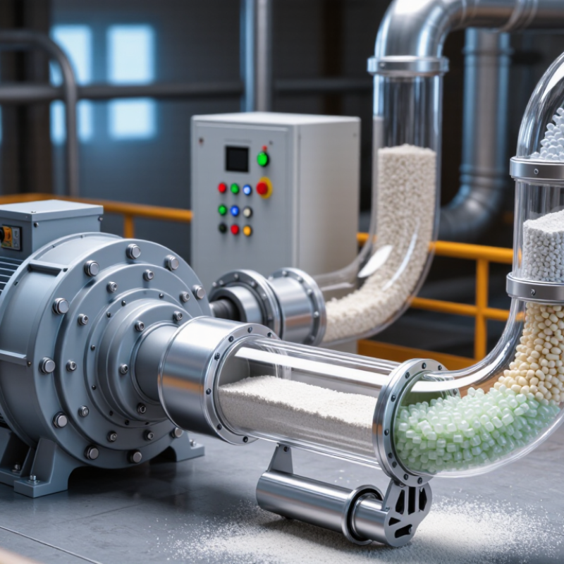
Before selecting a pneumatic conveying blower, define the material and conveying mode. In dilute-phase systems, air commonly travels at 15–30 m/s. This range is a starting point, not a universal setting. A fine, dry powder may suspend easily, while coarse granules need more velocity to stay moving. Too little air can let solids settle in elbows or horizontal pipe runs. Too much can increase abrasion, particle breakage, and energy use. The difference may show up as a dusty filter, worn bends, or unstable feeding. Small details matter.
Tips: Confirm particle size, bulk density, moisture, and conveying distance. Ask operators where deposits or plugging occur. Estimate line losses using the actual pipe layout, bends, pickup point, and receiver. Then verify airflow and pressure against blower curves, allowing for filters and changing material conditions. A pressure reading alone is not enough; air volume matters too.
Keep a modest operating margin, but avoid oversized equipment chosen “just in case.” Test with representative material where possible, and record pressure, flow, and feed rate during commissioning. The 15–30 m/s range can shift with particle shape and line design. I would not trust a clean calculation if plant data says otherwise; that mismatch deserves another look. Real lines vary.
Estimate Airflow and Pressure from Pipe Size, Route, and Solids Feed Rate
Begin with the pipe’s internal diameter, not just its nominal size. The diameter sets the conveying area, while the solids feed rate helps determine how much air must keep material moving. Record the target feed in kilograms per hour and note the material’s bulk density, particle size, and moisture. These details matter. Small changes can affect flow behavior.
Map the full route, including vertical lifts, elbows, flexible sections, pickup points, and filters. Each adds resistance, so pressure demand is not based on straight-pipe length alone. Estimate airflow and pressure together, using conveying data suited to the material and checking that air velocity stays within a workable range. Too little velocity may let solids settle; excessive velocity can increase wear and damage fragile material. Allow for pressure losses through separators and filters, too. A calculation is only a starting point: real material varies between batches, and moisture can shift performance. Confirm the estimate with operating measurements, such as inlet airflow and pressure under the intended feed rate.
Compare Blower Types: Roots Units Commonly Handle Low-Pressure, High-Volume Duty
A Roots blower is often a practical choice when a pneumatic conveying line needs steady, high airflow at relatively low pressure. Its rotating lobes move air through the system, making it well suited to many dilute-phase applications. Think of a long pipe carrying light powder: the blower must maintain enough airflow to keep particles moving, not simply produce the highest pressure. That distinction matters.
Compare the blower’s rated flow and pressure at your actual operating point, rather than relying on a headline capacity. Pipe length, bends, pickup design, and filter resistance all affect demand. A filter that gradually loads with dust can raise system pressure and power use. Small details add up. Roots units can also produce pulsation and noise, so check whether the installation needs a silencer or other controls. They may be a poor fit when the process requires unusually high pressure or very quiet operation. Conveyed material, temperature, and duty cycle should be reviewed with a qualified system designer. Early estimates can miss real-world resistance; that is worth checking before purchase.
Check Dense-Phase Requirements: Typical Conveying Velocities Can Be 5–10 m/s
Dense-phase conveying moves bulk solids through a pipeline at relatively low air velocities. Typical conveying velocities can be 5–10 m/s, but this range is a design reference, not a guarantee. Material often travels as plugs or dense pockets rather than a fast, uniform stream. This can reduce particle damage and airborne dust. Small details matter.
Choose a blower by checking airflow and pressure together, not velocity alone. Include pipe length, bends, elevation changes, feeder losses, and the pressure needed to keep solids moving. A coarse, heavy material may behave differently from a fine powder, even at the same velocity. If air speed falls too low, plugs can stall and pressure may rise. If it is too high, the system may behave more like dilute-phase conveying. Numbers need context.
Use material test data where possible, and confirm the operating point against the blower’s performance curve. Record the solids feed rate and check whether it stays steady during startup and normal operation. This estimate is imperfect: moisture, particle size, and feed consistency can shift the result. Allow room to adjust airflow and pressure during commissioning, rather than treating 5–10 m/s as a fixed target.
Verify Motor Power, Filtration, Temperature, and Noise Against Site Limits
How to Choose a Pneumatic Conveying Blower
Match motor power to the required airflow and pressure at the conveying line, not just the blower’s nameplate rating. Include filter resistance, pipe bends, elevation, and expected material changes in the calculation.
DOE’s 2003 Improving Fan System Performance sourcebook estimates fan systems use about 7% of U.S. manufacturing electricity. That figure is not a blower-sizing rule, but it makes avoidable oversizing worth checking. Small margins matter.
Verify the motor’s duty rating and site-specific limits, including voltage, altitude, and ambient temperature. A selection that works on paper may struggle in a hot equipment room.
Choose intake filtration for the dust and conditions around the installation, then check pressure drop as the filter loads. A clogged element can reduce airflow and raise operating strain. Record inlet and discharge temperatures during a representative conveying run; compare them with limits for the conveyed material, seals, and nearby equipment. Do not assume a cool morning test represents a summer shift.
Noise needs a measurement at the operator’s position, with doors and guards in their normal state. NIOSH’s 1998 Criteria for a Recommended Standard: Occupational Noise Exposure recommends an 85 dBA limit over eight hours, using a 3 dB exchange rate.
A phone app can flag a concern, but it cannot replace a calibrated sound-level meter. Noise travels. Keep room reflections and other machinery in mind when interpreting readings.
