INTERNATIONAL FLUID POWER, INC.

The Experts for Hydraulic Power Units, Components, and Custom Hydraulic Systems
Slider

7 Tips for Choosing a TCU Temperature Controller Machine

Choosing a TCU Temperature Controller Machine is not simply a matter of comparing heating power or purchasing price. In real production, small temperature changes can affect surface finish, cycle time, material stability, and rejected parts. A machine may look impressive on paper but perform poorly beside a long mold line, where hoses lose heat and pumps face constant resistance.

John W. Bozzelli, a respected injection-molding consultant, has often stressed the importance of process discipline: “Control the process, not just the machine.” That principle guides this practical introduction to seven essential selection tips. The right TCU Temperature Controller Machine should match the required temperature range, heating and cooling capacity, fluid type, flow rate, sensor accuracy, and operating environment. Safety functions also deserve attention, including low-fluid protection, over-temperature alarms, pressure monitoring, and automatic shutdown.

Look beyond the brochure.

Ask how quickly the unit responds after mold changes. Check whether replacement pumps, heaters, and controllers are readily available. Review service records, not only performance claims. An oil-based system may suit higher temperatures, while a water-based unit can provide faster response in other applications. However, the choice is rarely perfect. Energy use, maintenance effort, installation space, and operator training may conflict. That is where careful testing becomes valuable. A short trial under actual production conditions can reveal unstable readings, noisy pumps, or inconvenient controls before they become expensive problems.
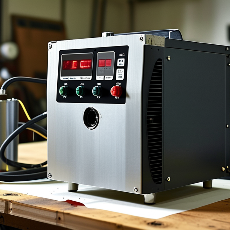
7 Tips for Choosing a TCU Temperature Controller Machine

Understanding TCU Temperature Controller Machines and Their Core Functions

7 Tips for Choosing a TCU Temperature Controller Machine

A TCU temperature controller machine regulates process temperature through heating, cooling, and controlled fluid circulation. It usually combines a pump, heat exchanger, sensors, valves, and a digital control system. The controller compares the measured temperature with the selected setpoint. It then adjusts heating or cooling output to reduce variation.

Control is the point.

When choosing a TCU, check its temperature range, heating capacity, cooling capacity, and circulation flow. A machine may reach a high temperature but respond slowly under production load. Look for stable control during startup, shutdown, and sudden material changes. Sensor accuracy also matters. A small reading error can affect viscosity, curing, molding quality, or product consistency.

Examine the fluid path carefully. Confirm that seals, pipes, and fittings suit the chosen heat-transfer fluid. Ask about over-temperature protection, low-flow alarms, pressure monitoring, and emergency shutdown functions. These features support safer operation and simpler troubleshooting.

A clear interface helps operators identify a blocked line or weak pump quickly. Maintenance access should not be overlooked. Filters, sensors, and heat exchangers eventually need inspection.

A compact design may save floor space, but it can make service awkward. That trade-off deserves honest review. Running a short trial with real operating conditions is often more reliable than selecting equipment from specifications alone.

Test it. Watch the trend.

Identifying the Temperature Range and Control Accuracy You Need

Choosing a TCU temperature controller machine starts with the process, not the catalog. Define the lowest and highest temperatures your application truly requires. Write down the target range. A process may run at 80°C, yet its startup and cleaning cycles may reach 120°C. Choose a controller with enough headroom, but avoid an oversized range. Excess capacity can reduce heating efficiency and increase operating costs. Thermal fluid type, flow rate, vessel size, and insulation also influence the achievable temperature.

Control accuracy is different from display resolution. A screen showing 0.1°C does not guarantee stable control within 0.1°C. Ask for measured accuracy, temperature stability, sensor tolerance, and response time. A practical specification might require ±0.5°C at the product, not merely at the heater outlet. Sensor placement matters greatly. A probe near the inlet can report a different temperature from one inside the working zone. Test conditions should match real production loads.

In practice, I would request performance data under minimum, normal, and maximum loads. Check overshoot during startup and recovery after a cold material charge. Small details matter. Calibration records should be traceable and current. I once treated the controller’s stated range as the main decision point, then found that slow recovery affected the process more than maximum temperature. That mistake is easy to repeat. Leave room for seasonal ambient changes, fluid aging, and future process adjustments. Reconsider the specification before purchasing.

Matching Heating and Cooling Capacity to Your Process Requirements

7 Tips for Choosing a TCU Temperature Controller Machine

Matching heating and cooling capacity to your process starts with the real thermal load, not the machine’s advertised maximum. Calculate product mass, specific heat, temperature change, cycle time, and heat loss from tanks, piping, and fittings. A 500-kilogram batch needing a 40°C rise in 30 minutes requires far more heating power than the same batch heated over two hours. Include mixing energy and incoming material temperature.

Cooling is often underestimated. The U.S. Department of Energy’s Industrial Decarbonization Roadmap reports that process heating represents about 51% of industrial energy use. The IEA’s Energy Efficiency 2023 report also identifies industry as using roughly 37% of global final energy. These figures show why poor capacity matching can create costly energy waste. Select heating and cooling capacities independently when possible. A unit may heat quickly but remove heat too slowly after an exothermic reaction.

Leave a practical margin, usually around 10% to 20%, after calculating the steady and peak loads. Excessive oversizing can cause short cycling, unstable temperatures, and unnecessary capital cost. Undersizing creates long recovery times and rejected batches. I have seen specifications based only on vessel volume. That approach is convenient, but incomplete. Check the fluid’s viscosity, allowable temperature range, pressure drop, and seasonal utility conditions. ASHRAE guidance stresses that equipment performance depends on operating conditions, not rating-plate values. Request capacity curves at your actual supply and return temperatures. Test the machine during commissioning with logged temperatures, flow rates, and recovery time. Small details matter.

Evaluating Fluid Compatibility, Flow Rate, and System Connections

Choosing a TCU Temperature Controller Machine

A TCU should match the process fluid, not merely the target temperature. Check compatibility with wetted metals, seals, hoses, and pump materials. Water-glycol blends may need different seals than thermal oil. Read the fluid safety data and the controller’s operating limits. Small details matter. I once saw a test loop develop cloudy fluid after an elastomer swelled. The temperature readings stayed normal, but circulation weakened. That assumption was wrong: stable temperature does not prove chemical compatibility. Ask for immersion data when the fluid is unfamiliar.

Flow rate affects heat transfer, response time, and temperature uniformity. Compare the machine’s rated flow with the process pressure drop, not with pipe size alone. A narrow mold channel can restrict circulation even when the pump rating looks impressive. Measure flow at operating temperature if possible. Cold-fluid readings can mislead. Leave some margin for filters, bends, and gradual fouling. More flow is not always better; excessive velocity can create noise, vibration, or unnecessary wear. A simple flow meter is often worth the installation cost.

Inspect every connection before approval. Confirm port size, thread standard, hose material, drain location, and service access. Mismatched threads can leak slowly. That is harder to detect. Keep supply and return lines clearly identified, and avoid sharp hose bends near hot surfaces. During commissioning, record inlet temperature, outlet temperature, pressure, and actual flow. Repeat these checks after several operating cycles. I would challenge the specification twice, because a convenient connection on paper may be awkward beside the equipment. Reliable selection comes from measured conditions, not catalog confidence.

7 Tips for Choosing a TCU Temperature Controller Machine - Evaluating Fluid Compatibility, Flow Rate, and System Connections

Tip Selection Dimension Recommended Check Typical Reference Data Why It Matters Acceptance Criteria
1 Define the Required Temperature Range Compare the process setpoint, normal operating range, heating requirement, and cooling requirement with the controller's rated operating range. Common liquid TCU applications operate from approximately 5°C to 160°C; specialized systems may operate outside this range. A unit that reaches the setpoint but cannot provide sufficient heating or cooling capacity during production changes may cause long cycle times or unstable temperature control. Required setpoint is within the rated range, with additional operating margin for ambient conditions and process transients.
2 Verify Fluid Compatibility Identify the heat-transfer fluid, concentration, operating temperature, viscosity, flash point, and compatibility with wetted metals, seals, hoses, and pump components. Water is commonly used near 5°C to 95°C. Water-glycol mixtures are often selected for freeze protection. Thermal oils are used for higher-temperature service, subject to their specified limits. Incorrect fluid selection can cause corrosion, seal swelling, pump damage, reduced heat transfer, deposits, or a fire hazard at elevated temperatures. Fluid supplier data, safety documentation, and TCU wetted-material specifications show compatibility at the complete operating temperature range.
3 Match Flow Rate and Pressure Calculate the flow needed to remove or supply the process heat load, then check pump capacity at the actual system resistance and fluid viscosity. Small and medium process circuits commonly use approximately 10–200 L/min. Pump pressure may range from about 2–6 bar, depending on the circuit and temperature. Insufficient flow reduces heat-transfer performance and creates temperature differences between the TCU outlet and the process return. The duty point, including flow and pressure, falls within the pump curve with adequate margin and without excessive pressure drop.
4 Check Process Connections Confirm connection size, connection type, flow direction, hose routing, sealing method, and the distance between the TCU and the process equipment. Typical connection sizes range from approximately DN15 to DN50 for many compact and mid-sized circuits. Common options include threaded, flanged, and sanitary connections. Mismatched connections can require restrictive adapters, increase leakage risk, introduce contamination, or make installation and maintenance difficult. All connections match the process piping or have approved adapters, and hoses are rated for the fluid, pressure, and temperature.
5 Size Heating and Cooling Capacity Estimate the process heat load from material mass, specific heat, temperature change, cycle time, heat loss, and any exothermic or machine-generated heat. A basic estimate is Q = m × Cp × ΔT ÷ t. Allowance for heat loss and process variation is commonly added after the base load is calculated. A controller with inadequate capacity may recover slowly after loading changes, while excessive capacity can increase cost and make low-load control more difficult. Rated heating and cooling capacity covers the calculated load at the required temperature, flow rate, and ambient conditions.
6 Evaluate Control Accuracy and Safety Review sensor type, control accuracy, response time, over-temperature protection, low-level protection, pressure protection, alarms, and emergency shutdown functions. Many industrial temperature-control applications target approximately ±0.5°C to ±1.0°C process stability, depending on sensor placement and system dynamics. Accurate sensing and independent safety functions protect the process, equipment, fluid, and operators from overheating, dry running, and abnormal pressure. Control performance meets the process tolerance, and all required alarms and protective interlocks are available for testing before commissioning.
7 Confirm Utilities, Installation, and Maintenance Needs Check electrical supply, cooling-water or compressed-air requirements, footprint, ventilation clearance, drain access, noise level, fluid filling, filtration, and service access. Electrical supplies commonly include 230 V or 400 V AC, depending on heater and pump power. Utility flow and pressure must be verified from the equipment design data. A correctly sized TCU can still underperform if utilities are undersized, airflow is restricted, filters are blocked, or routine draining and inspection are difficult. Site utilities meet the calculated demand, installation clearances are maintained, and routine inspection, draining, cleaning, and calibration can be performed safely.

Note: Reference ranges are general engineering guidelines. Final selection should be based on the actual process heat load, fluid properties, pump curve, connection standards, utility conditions, and applicable safety requirements.

Comparing Safety Features, Energy Efficiency, and Maintenance Needs

7 Tips for Choosing a TCU Temperature Controller Machine

Comparing Safety Features, Energy Efficiency, and Maintenance Needs

A reliable TCU should protect the process, the operator, and nearby equipment. I compare safety features before purchase price. Check the temperature range, pressure rating, and fluid compatibility against real operating conditions. Independent over-temperature protection deserves priority. Look for flow-loss detection, pressure alarms, emergency shutdown, and clear fault messages. Test whether alarms remain visible near loud machinery. Some interfaces look impressive but hide critical warnings.

Energy Efficiency

Energy efficiency is more than a low-power label. Ask for pump power, heater cycling behavior, and cooling demand at your actual setpoint. Variable-speed pumps can reduce consumption during stable production. Insulated hoses and short connections also limit heat loss. Measure electricity during startup, steady operation, and standby.

One small mistake matters. Comparing only the heater rating can produce a misleading estimate. Confirm that standby mode does not disturb temperature stability.

Maintenance Needs

Maintenance needs deserve equal attention. Choose drain points that avoid splashing electrical parts. Check filter access, seal replacement space, and service record availability. A sight glass can reveal cloudy fluid or unexpected flow changes. Schedule inspections before failure occurs. Keep calibration checks documented, even when readings seem normal.

I once ignored a slightly noisy pump. It later caused unstable flow. That was avoidable. Leave space around the machine, label hoses clearly, and train operators to record alarms, repairs, and unusual temperature drift.