International Fluid Power Inc.
International Fluid Power - Innovative Partners For Global Sourcing Of Fluid Power Products. Your Complete Hydraulic Source in SE Minnesota.

What Is a Cleanroom Chiller System?
A Cleanroom Chiller System does more than cool equipment. It helps maintain stable temperatures and humidity while supporting the controlled conditions needed in clean manufacturing spaces. Its performance can affect product quality, process consistency, and staff comfort. Small shifts matter.
Cleanroom technology author William Whyte has written extensively about contamination control and cleanroom design. His work emphasizes that cleanliness depends on controlling air movement and the sources of contamination, not merely installing filters. That is a paraphrase of his published work, not a verified direct quotation. The distinction matters: technical guidance should be traceable, not dressed up as a quote.
In practice, a chiller serves the cleanroom’s HVAC system by removing heat from air-handling equipment and process loads. Picture a production room with steady airflow, sensitive instruments, and warm motors running through a long shift. A poorly matched chiller may struggle with changing loads, cause temperature drift, or waste energy. Yet capacity alone does not guarantee good control. Pipe layout, redundancy, maintenance access, and coordination with air handlers all shape real-world performance. Even a carefully designed system can reveal weaknesses after commissioning. That deserves honest review.
This introduction outlines what a Cleanroom Chiller System is, how its main components work, and which design choices deserve close attention. It also considers operation and maintenance, where small checks—such as inspecting alarms and reviewing temperature trends—can prevent larger disruptions. Readers should use project-specific engineering and applicable standards when planning a system.
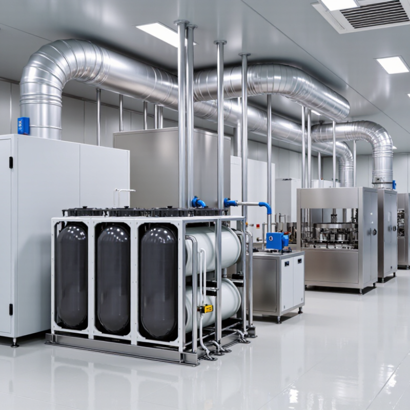
Definition and Purpose of a Cleanroom Chiller System
A cleanroom chiller system removes heat from chilled water and circulates it to air-handling coils or process equipment. Its purpose is to maintain stable temperature and support humidity control while the room’s filtration and airflow systems manage airborne particles. The chiller does not make a room clean by itself. That distinction matters.
ISO 14644-1:2015 sets particle concentration limits by cleanroom class. For particles at least 0.5 micrometres wide, ISO Class 7 allows up to 352,000 particles per cubic metre. Class 8 allows 3,520,000. These figures show why room classification matters, but they do not determine cooling capacity. Designers must also account for people, lighting, equipment heat, outdoor air, and moisture loads.
In practice, chilled water flows through coils above the clean space, while sensors monitor supply-air temperature and room conditions. A poorly balanced system can create hot spots near equipment or make humidity harder to control. Small changes matter. ASHRAE’s Handbook—HVAC Applications discusses environmental control for clean spaces; its guidance supports treating cooling, airflow, and pressure as coordinated design tasks. Still, actual performance depends on commissioning and ongoing checks. A neat design drawing cannot reveal every door opening or shifting production load.
| Dimension | Definition or Typical Information | Purpose and Design Considerations |
|---|---|---|
| System definition | A cleanroom chiller system is a cooling plant that removes heat from water or another approved fluid and circulates the cooled fluid to equipment such as air-handling coils or process equipment. | It provides a controlled source of cooling for cleanroom environmental systems and, where required, manufacturing processes. |
| Main purpose | The system helps manage room temperature and heat loads from people, lighting, equipment, outdoor air, and manufacturing processes. | Stable temperature can support product quality, equipment operation, and repeatable environmental conditions. A chiller alone does not establish cleanroom cleanliness. |
| Typical system components | Common components include a chiller, pumps, piping, control valves, sensors, and heat-exchange coils. Heat rejection may use a cooling tower or an air-cooled condenser, depending on system design. | Component selection depends on cooling load, site conditions, water availability, redundancy needs, and maintenance access. |
| Cooling distribution | Chilled fluid is circulated through coils in air-handling units or terminal equipment, where it absorbs heat from air or a process loop. | Correct flow, coil capacity, insulation, and control-valve operation help deliver the required cooling while limiting unwanted heat gain and condensation. |
| Temperature and humidity relationship | Cooling coils can also remove moisture from air when their surface temperature is below the air’s dew point. The required supply-water temperature depends on the coil, airflow, load, and humidity-control strategy. | Temperature and humidity targets should be set for the specific process and facility. There is no single chilled-water temperature suitable for every cleanroom. |
| Cleanliness control | Air cleanliness is primarily managed through measures such as filtration, airflow design, pressure relationships, and operating procedures—not by the chiller itself. | The chiller supports environmental control by meeting cooling demand. It should be coordinated with the air-handling and cleanroom control systems. |
| Common applications | Chiller systems may serve cleanrooms in industries such as pharmaceutical manufacturing, medical-device production, electronics, laboratories, and other controlled manufacturing environments. | Different processes can have different temperature, humidity, and heat-load requirements, so the system should be selected for the actual application. |
| Capacity and sizing | Cooling capacity is determined from a load assessment that considers room and process heat gains, ventilation requirements, operating schedules, and expected future loads. | Oversizing or undersizing can affect efficiency, control stability, and operating cost. Capacity should be established by qualified project engineers using site-specific data. |
| Controls and monitoring | Controls commonly monitor temperatures, fluid flow, equipment status, and alarms. Depending on the facility, data may be integrated with a building-management or facility-monitoring system. | Monitoring helps operators identify abnormal conditions and maintain reliable cooling. Alarm limits and records should reflect facility requirements. |
| Reliability and maintenance | Routine maintenance may include inspection of heat exchangers, pumps, filters or strainers, fluid quality, sensors, and control devices, following the equipment and facility maintenance plans. | Critical facilities may evaluate standby capacity or redundant equipment to reduce the impact of a chiller outage. The appropriate arrangement depends on risk and operational needs. |